Three parallel-running tunnels constitute what we know as the ‘’Channel Tunnel’’. A 15.7-foot wide service tunnel is flanked on either side by a 24.9-foot diameter single-track running tunnel. The trio of bores measure some 31.35 miles in length, of which 24 miles is directly under the English Channel. The service tunnel accommodates a two-way road used by the diesel-powered ‘’Service Tunnel Transportation System’’ (STTS) vehicles, these of which can be steered manually or by computer. The running tunnels are designated as ‘’South’’ and ‘’North’’; the former accommodates Britain-bound services, and the latter operates in the reverse. Commencement of ‘’Chunnel’’ boring began with the centrally positioned service tunnel, work starting from the British end on 15th December 1987. On 28th February of the following year, boring of the same tunnel began from French soil. Starting with these works was the construction of two huge terminal sites on each side of the Chunnel system for vehicle shuttle services – one at Cheriton, Folkestone, and the other at Coquelles, Calais.
The site selected for the British terminal resided at the foot of the North Downs, bordered to the west and south by the villages of Newington and Cheriton respectively. From east to west the terminal site stretched for 1⅔-mile, and the total area covered was 346 acres; so restricted was the land that the adjacent village of Newington was to see its eastern peripheral swallowed up in the development work. On the other side of the Channel, the French were not subject to such space limitations. A vast green field area presented itself to the west of Calais, which could accommodate a terminal area five times the size of its British counterpart, at some 1730 acres. Consequently, the decision was taken to incorporate the main 100,000 square foot heavy maintenance depot at Coquelles, although smaller facilities would be available at Cheriton. Construction at the latter had begun with the levelling and stabilising of the site. A 3½-mile underwater pipeline was laid between Deal and Goodwin Sands, the latter of which was a twelve-mile-long, five-mile-wide sand embankment lying off the Kent Coast. Sand from here was dredged for the stabilisation task, and it avoided the need to carry out any inland excavations. Nevertheless, were there any excavations which needed refilling, there was plenty of soil with which to do it. The British tunnelling operation was producing no less than 2400 tonnes of waste soil every hour when the tunnel boring machines (TBM) were rotating at top speed. A proportion of this earth could be used to landscape the Cheriton terminal site, but most of it was earmarked to create an artificial platform in the sea, extending from the construction site at Shakespeare Cliff.
At Cheriton, eight concrete-built island platforms, 865 yards in length and averaging 12 yards in width, were to be provided. The need to load and unload vehicles from trains quickly and easily meant that each island platform was to be separated from the next by just a single-track, allowing access to trains from either side. The islands were to be linked by four concrete bridges straddling the tracks: one at either end of the platforms, and another two in a roughly central position, mid-way up the islands. The western pair of overbridges were for cars and HGVs bound for a shuttle, whilst the eastern pair were to be used by those vehicles disembarking from trains. The longest shuttles of all, those for freight, were to be constituted of two rakes of fourteen wagons each, a trio of loading/unloading wagons, and top-and-tailing locomotives. Passenger shuttles would be constituted of two rakes of twelve vehicles each; one rake would be single-decked, the other double-decked, these carrying cars and coaches respectively. In addition to these vehicles and the top-and-tailing locomotives would be two unloading wagons with telescopic hoods: one at the front of the formation, and another sandwich in-between the two rakes. With reference to the latter, those vehicles embarking/disembarking midway up the train could utilise the middle bridges, eliminating the need to traverse any significant length of the platform surface. Attention should be drawn to the fact that at Coquelles, although eight platform faces were to be available, these would be formed from just four islands. Thus, the islands would be separated from each other by a double-track, and vehicles would only be able to access shuttles from one side.
The entire Eurotunnel railway system was planned to form a giant figure of eight. This permitted continuous running of trains and eliminated the need for reversals after termination. For example, when a train arrived at Cheriton from Coquelles, it would first be sent round a curve at the western extremity of the terminal to double-back on itself; therefore, when it entered the platforms, the locomotive which hauled the shuttle from France would be hauling it back again, in turn leaving the same Tri-Bo locomotive trailing at the rear. Notice that the arrangement is described as a figure of eight, rather than a plain oval. At Cheriton, Shuttles would round the curve in a clockwise direction, whilst at Calais, the presence of a diamond crossing (formed by a pair of back-to-back Y-points) would result in trains changing course and rounding the curve in an anti-clockwise direction. The thinking behind this ‘’eight’’ rather than ‘’oval’’ arrangement was to equalise the wear of the wheel flanges on each side of the locomotives and rolling stock. The curves at British and French terminals measured 0.62 and 1.06 miles in length respectively, and the smaller scale of Cheriton compared with its Coquelles counterpart also meant that the curve negotiated would be much tighter. Such a curve radius was partly the reason for procuring a shuttle locomotive with a Bo-Bo-Bo wheel arrangement – i.e. three bogies of two axles each. The purpose of these arrival curves was also to aid the slowing down of the shuttle trains, a decided advantage over standard end-to-end terminating arrangements, which relied wholly on brakes. As part of the re-landscaping of the Cheriton terminal area, to protect the adjacent Newington village from noise, the arrival loop – which was destined to become double-track – would dive into a tunnel through an artificial embankment. The tunnel also allowed the loop to pass under the approaching tracks from London, and upon part of the embankment, at the south west corner of the site, terminal check-in facilities could be constructed. These eventually comprised fourteen booths – arranged in a gentle curve formation running north to south – protected by a 290-foot long ridge-and-furrow canopy. To the north of these facilities were to be further check-in booths and parking lanes for HGVs, again constructed above the arrival loop line.
Further to the landscaping works already mentioned, environmental procedures also saw the erection of towering black fences within, and on the edges of, the terminal. Similar fences had been included within the Dollands Moor Freight Yard construction programme, and their raison d’être was to act as a sound barrier, in addition to preventing wild animals roaming on the tracks. Around the perimeters of the Cheriton and Dollands Moor sites, as part of the landscaping effort, a total of 500,000 new trees were planted.

A northward view from the observation tower at Cheriton Eurotunnel Exhibition Centre shows that the gigantic viaducts linking the platforms were in place and that the track bed had been prepared, but rails had yet to be laid. The construction site in the centre of the picture was to become the diesel-electric maintenance depot. The North Downs form the backdrop. © David Glasspool Collection

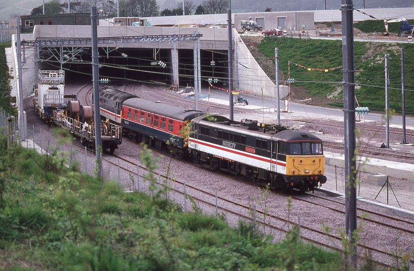
An eastward view shows that, since the previous photograph was taken, track had been laid and catenary masts installed. The maintenance depot, the site of which was seen in the previous photograph, had taken shape. The track in the foreground, curving to the left, is heading towards the tunnel that takes the railway underneath the village of Newington. © David Glasspool Collection
Return to the Kent Rail Homepage or alternatively, check for Updates.
Website & Copyright information - Links - Contact the Webmaster