

Chunnel Crossover Caverns
The fire of November 1996, which caused substantial damage to the South Running Tunnel, has already been mentioned, but incidents such as this do not necessarily bring complete closure to the full 31.35 miles of underground route. Enshrined within the original design specification was the requirement for trains to be able to switch between tunnels whilst under the English Channel. To enable this, the Chunnel was equipped with two ''crossover caverns'', each of which feature diamond crossings between the running lines to enable such a manoeuvre. The presence of two crossover points allowed each running tunnel to be divided into three separate sections - i.e. six separate parts combined. Primarily, this was to ensure that any maintenance work caused as little disruption as possible to services. Thus, when maintenance crews take possession of a section of tunnel for repair, they need only occupy one of the six divisions mentioned, allowing the other five sections to remain fully useable by trains. The tunnel is signalled for reversible running; therefore, a service can plunge into the Northern Running Tunnel at Cheriton, but emerge at Coquelles from the portal of the Southern Running Tunnel during maintenance possessions. Of the two caverns themselves, one is positioned eleven miles from the Cheriton tunnel portal, whilst the second is located nine miles from the Coquelles portal, and the pair are referred to as the British and French Crossovers respectively. The caverns vary in size, and their seemingly arbitrary placement within the tunnel results from the thickness of the surrounding chalk marl layer. The thicker the layer, the less likely the chance of the caverns collapsing or leaking water. Naturally, the very fact that these crossover points were within caverns meant that the two running lines were contained within one huge bore, rather than each having its own single tunnel. Thus, a thicker than normal chalk marl (a combination of chalk and clay) layer around the giant bore was imperative.
For the most part of the Channel Tunnel system, a 15.7-foot wide service tunnel is flanked on either side by a 24.9-foot diameter single-track running tunnel. However, for the crossover caverns, the two running tunnels had to be brought together, which involved slewing the smaller service tunnel to the north of these bores. At the crossovers, the two running lines can still be separated from each other by means of a pair of sliding doors, each of those within the British cavern measuring 105 feet in length and weighing 92 tonnes. Their main purpose is to separate the independent ventilation systems housed within each tunnel when the crossover is not in use. In the event of any fire in one of the running tunnels, the fire-resistant doors prevent the flames from spreading to the adjacent line. The doors are controlled by a room located within one of the two triangles created by the converging tracks. To negotiate the crossovers at a safe speed, all trains are required to slow to 38 MPH.

| British Crossover Cavern | French Crossover Cavern |
| Height | 31 Foot | Height | 40 Foot |
| Length | 512 Foot | Length | 530 Foot |
| Width | 59 Foot | Width | 62 Foot |
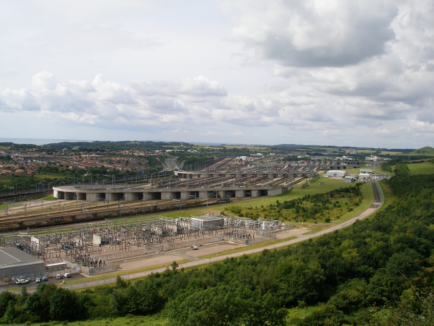
A westward view from the North Downs reveals the extensive terminal site, complete with the huge electricity sub-station in the foreground. The large concrete-built bridges, which link the road system with the terminal platforms, dominate the scene. In the background, left of centre, can be seen the M20, whilst to the right of this can just be seen the maintenance depot and sidings. © David Glasspool
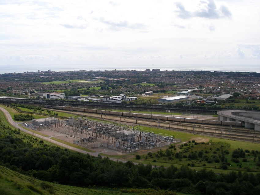
A southward view shows Folkestone in the background, with the English Channel beyond. A passenger shuttle is observed leaving the terminal: all twelve single-decked wagons of the first rake are in view. Hidden by the bridge support is the telescopic unloading wagon, which in turn is connected to the second rake of twelve vehicles, the latter being double -decked wagons. In the foreground is the electricity sub-station. © David Glasspool
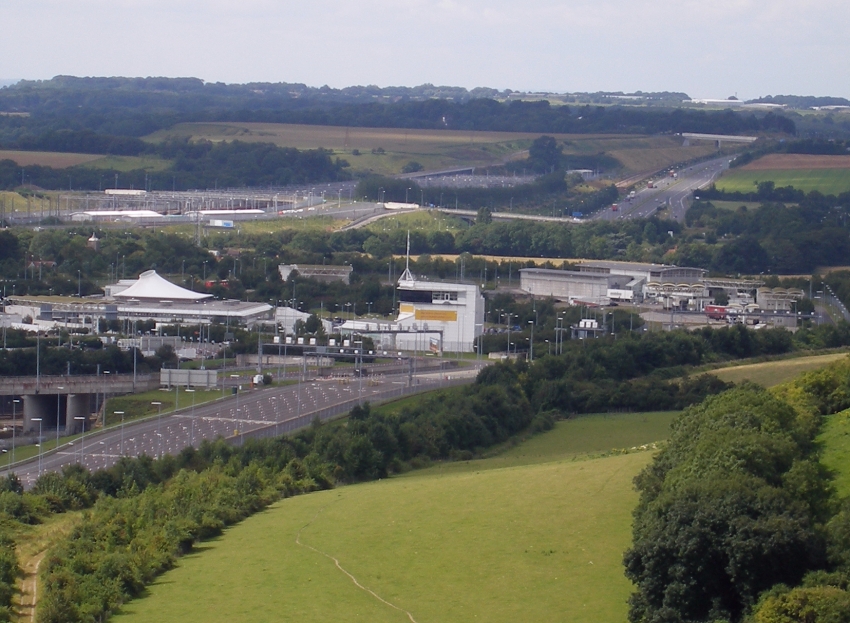
In view is the Cheriton Control Tower, which oversees the operation of the terminal's road and rail networks. It is home to the world's largest LED display panel, which illuminates a signalling diagram of the entire Eurotunnel system. © David Glasspool
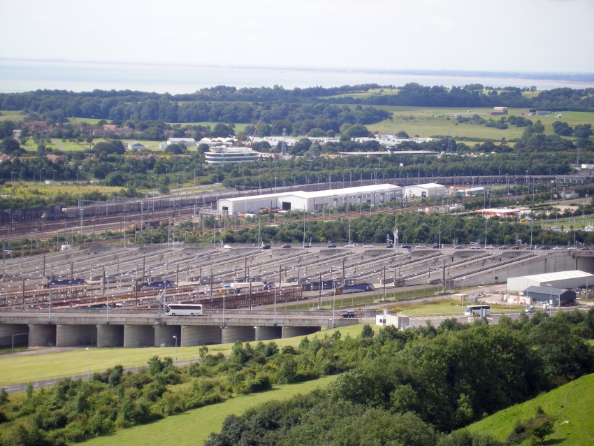
In the background of this view is the diesel-electric maintenance depot. Of the two main rail-served buildings, the largest measures some 475 feet by 75 feet, whilst the smaller structure is approximately 335 feet by 35 feet. From the outset, Eurotunnel had five diesel-electric locomotives, which were used for hauling maintenance trains through the tunnel, but also for rescuing stricken shuttles. The depot and shuttle stabling sidings are separated from the main terminal complex by the lines from the capital. © David Glasspool
Return to the Kent Rail Homepage or alternatively, check for Updates.
Website & Copyright information - Links - Contact the Webmaster