

London Victoria
Enter the East Kent Railway
A House of Commons Report of 22nd May 1855 stated that ‘’the impatience of the
gentlemen of the county of Kent’’ had led to the application for the
construction of a 48½-mile railway between Canterbury and Strood. The ‘’East
Kent Railway Act’’ was passed on 4th August 1853, and capital for the line was
organised as follows:
One individual in London was wholly responsible to provide £100,000 (£6,521,700 at 2007 prices)
A stock-broking firm was committed to £80,000 (£5,217,360 at 2007 prices)
The railway’s building contractor was to supply a further £72,000 (£4,695,625 at 2007 prices)
£253,500 (£16,532,515 at 2007 prices) in the form of shares and loans
The ‘’impatient gentlemen’’ were wealthy businessmen of Faversham. Having watched the SER construct a ‘’Weald of Kent’’ trunk line to Dover, in addition to witnessing the same company failing to extend its North Kent Line over the Medway to Rochester and Chatham, the group found its home town deprived of a vital railway link to the capital. In the same Parliamentary Report of 22nd May 1855, it had been made clear to the promoters that the proposed line would only be of use if it was extended to Dover (or, as it was then known, ‘’Dovor’’), thus providing a direct link between London and the Channel Port. As a result, an extension from Canterbury to Dover was authorised in that year, but things were already going awry in the East Kent Railway (EKR) camp. Parliament had noted, again in 1855, that the promoters of the EKR had adhered to not one of the conditions of the 1853 Act. It was also at this time that the company – already beset with money problems – came crawling to Parliament, requesting financial assistance, enabling it to complete the railway bridge over the River Medway. At this time, it was customary for the Government to impound 10% of the total capital assigned to a railway project, to guarantee the bona fides of the undertaking and that of its promoters. The money was deposited with the Court of Chancery, and for the EKR project, £50,550 was held. The Admiralty had also applied to Parliament for the money to be released, for it was also interested in seeing the completion of the railway bridge over the Medway. Opening of the EKR was piecemeal:
Chatham to Faversham: 25th January 1858
Chatham to Strood: 29th March 1859
Faversham to Canterbury: 9th July 1860
Eastward extensions to Thanet had also been commissioned, and although covered extensively in other sections of the website, it is worthy repeating opening dates, if only for the sake of completeness:
Whitstable to Herne Bay: 13th July 1861
Canterbury to Dover: 22nd July 1861
Herne Bay to Ramsgate: 5th October 1863
The EKR had its
sights set on the proposed West End terminus of the VS&PR, and to get there, the
company intended running over the SER’s 1849-opened North Kent Line, which in
turn could provide access to the metals of the WEL&CPR and, ultimately, the
station of the VS&PR. The EKR failed to acquire running powers over the North
Kent Line: the SER had countered such proposals, claiming that the route was
already running at full capacity and was unable to accommodate more traffic,
neither its own nor that of another company. As a result, the EKR was authorised
to forge an independent route to the capital, and in light of this, the company
was renamed the ‘’London Chatham & Dover Railway’’ on 1st August 1859.
Bridging the Gap
The Victoria Bridge (or, alternatively, Grosvenor Bridge) was the first to carry
a railway across the Thames. In September 1858, work commenced on dredging the
gravel from the site of the proposed river piers, and on the 10th October of the
same year, piling of the cofferdams and gantries began. Cofferdams were
temporary watertight enclosures which could be pumped dry to permit construction
to take place under standard dry conditions. Three piers would eventually span
the Thames, and the first stone was laid on the northern of these on 9th June
1859. Erection of ironwork began on 28th February 1860, and the bridge was a
product of John Fowler, the VS&PR’s Engineer in Chief, and William Wilson, the
Assistant Engineer. The building contractor was Mr Kelk, who was also
responsible for the construction of both Victoria terminus stations and the
Grosvenor Hotel.
The bridge cost a total of £90,000 to build, equating to £3.00 per square foot.
The quantities of materials used in the construction of the bridge were as
follows:
197,800 cubic feet of timber, used temporarily in gantries and cofferdams; 16,800 cubic feet of this was used in floors
10,700 cubic feet of York landings
4050 cubic yards of concrete
6500 cubic yards of brickwork
23,857 cubic feet of Portland Roach Stone
57,205 cubic feet of Bramley Fall Stone
1296 tons of wrought iron
225 tons of cast iron
The bridge extended
for a total length of 920-feet and comprised two stone abutments on each side of
the river, with three piers within the Thames, all of which supported four
arched spans of 175-feet length each. There were two land openings, one at each
end of the bridge, which had a span of 70-feet and carried the railway above the
roads at a height of 16-feet. Each arch rose up to a peak of 22-feet above
Trinity high water level, and between the latter and the springing of each arch
(i.e. where the arch left the pier) existed a height of 4-feet 6-inches. Thus,
each arch alone measured 17-feet 6-inches from top to bottom.
At the riverbed, the three piers were each 18-feet wide, tapering to 12-feet by
the time the iron framework of the arches was met. Piles for the foundations
were sunk to a depth of 15-feet below the layer of clay in the riverbed (30-feet
below high water level), and cofferdams used to drain water. The foundations of
the river piers were subsequently driven into solid clay to a minimum depth of
8-feet, and a 4-foot-thick concrete bed was laid. The latter was formed by using
one part of Portland Cement to seven parts of clean river gravel. Upon the
concrete were set two layers of Yorkshire Rag Stone, each of which was one-foot
thick, and on top of this was placed a layer of brickwork, set in cement, rising
to a height of 18-inches below the lowest water level. Between the lowest water
level and the springing of the arches, the piers were faced with Portland Roach
Stone, set in lias, a form of limestone. Above the springing of the arches, the
masonry became faced with Bramley Fall Stone, obtained from near Leeds, and this
was used to create various mouldings and ornaments along the bridge.
Each arch comprised six curved ribs of wrought-iron, affixed to cast-iron
bedplates set into the masonry of the bridge piers. Between the parapets of the
bridge existed a width of 32-feet, allowing the structure to accommodate a
double-track line of mixed gauge. The rails were carried at a height of 24½-feet
above Trinity high water level, and the strength of the bridge was tested on 9th
June 1860. This involved placing a locomotive, coupled to fully laden trucks,
upon the bridge, creating a total weight of 350 tons
Terminus: Design and Construction
Worker strike action in autumn 1859 delayed construction work. However, on 28th
February 1860, the directors of the VS&PR declared in ‘’The Times’’ newspaper
that ‘’the works of the line and bridge are now so advanced as to leave no doubt
of their completion by the appointed time’’. The directors had also submitted a
Bill to Parliament for the absorption of the VS&PR by the LB&SCR, with an aim to
dissolve the former by 1st June 1861. By this time, the GWR had come on the
scene, and the company intended operating additional services to Reading and
Windsor from Victoria. GWR services were predominantly Broad Gauge and capacity
at Paddington had already reached saturation point. A circuitous route to
Victoria was to be forged, which would see GWR services twice pass over the
Thames (more of later).
To preserve the exclusiveness of Belgravia and Pimlico, landowners required that
the terminus approaches be covered for half a mile by a light iron glass roof.
Furthermore, to minimize the sound made by passing trains, thick sheets of
vulcanised India rubber had to be laid in-between the rails and the longitudinal
sleepers. Such restrictions prevented an architectural masterpiece being
produced, and particularly from the entrance façade, the terminus eventually
looked like a hotchpotch of temporary structures. The ‘’Brighton’’ station was
designed by Robert Jacomb Hood, engineer of the LB&SCR, and comprised a
ridge-and-furrow roof, supported upon a brick wall to the west and two rows of
iron columns to the east, covering a dozen platforms and ten tracks. The station
comprised 10,400 square yards of departure platform and 4,450 square yards of
arrival platform, and the total capital made available for the construction of
the terminus had been £676,000 (about £49,500,000 at 2007 prices). It was
1000-feet in length and 480-feet at its widest point, and covered an area of
about eleven acres. The trainshed rose up to an unimposing height of 40-feet,
formed of sixteen spans of 50-foot width and 230-foot length. Waiting rooms and
booking offices were erected at the head of the station, beyond the buffer
stops, and separate platforms (about two feet above rail level) and offices were
provided exclusively for Crystal Palace traffic, to alleviate overcrowding. The
station’s northern façade comprised a pair of canopies: the larger of the two
measured 100-feet in length by 40-feet in depth, and was constituted of a trio
of rectangular sections. The second, smaller canopy was positioned to the west
of its larger counterpart, and measured about 65-feet in length by 35-feet in
depth.
The Brighton station formally opened to traffic on 1st October 1860. Closure of
the Pimlico terminus, south of the Thames in Battersea, had occurred on 30th
September 1860, but at this stage, the LC&DR had yet to get beyond Strood. This
it finally did when through running between Canterbury and Victoria commenced on
3rd December of the same year, but the company still lacked a proper terminus,
instead using temporary accommodation for 1½-years. LC&DR metals extended only
as far as St Mary Cray; between here and Shortlands (then known as ‘’Bromley’’),
the company ran over the rails of the Mid-Kent Railway, which at this time was
leased to the SER. These in turn led to the network of the WEL&CPR which,
naturally, provided access to Victoria: the route into London was a circuitous
one. Furthermore, the WEL&CRP had been absorbed by the LB&SCR on 1st July 1859,
thus the LC&DR found itself at the mercy of its neighbour at Victoria, and was
subject to access tolls. Problems soon arose with regards to train priority and
track usage, resulting in the LC&DR forging a completely independent route to
the West End terminus (more of later).
On 25th August 1862, the ‘’Chatham’’ station was deemed formally complete.
Compared with its ‘’Brighton’’ neighbour, it was somewhat more attractive,
solely as a result of a graceful trainshed. The station was designed under the
guidance of the VS&PR’s Consultant Engineer, John Fowler (Knighted in 1885). The
building contractor was one Mr Kelk, and the terminus was subsequently leased
jointly to the LC&DR and GWR. The lease was for a period of 999 years, and as
part of the agreement, none of the railway companies were required to pay tolls
to the VS&PR for use of the line over Grosvenor Bridge. The LC&DR was subject to
an annual rent of £32,000 at Victoria, and the GWR paid £18,000 per annum.
The pride of the site was indeed the aforementioned trainshed, which comprised
two arched spans of varying dimensions: the western span was the larger of the
two, measuring 129-feet by 385-feet, whilst its eastern counterpart measured
127-feet by 455-feet. The spans comprised an iron framework held together by tie
rods, and running along the eastern elevation of the trainshed were yellow-brick
offices, lined with Portland Stone, which were built to a height which met the
underhang of the eastern arched span. However, at the northern façade of the
‘’Chatham’’ station, it was the same old story. As per the ‘’Brighton’’ station,
passengers approaching the ‘’Chatham’’ site were presented with a hotchpotch of
single-storey structures, in the form of clapboard offices. As touched upon
earlier, residents of Pimlico had imposed severe restrictions on the railway,
which prevented any architectural extravagance. Perhaps as a consolation, the
twin-arches of the ‘’Chatham’’ trainshed could still be appreciated from the
north, as a result of single-storey timber façade structures. Whilst the two
termini stood side by side, there was no access between the two inside: they
were essentially two wholly separate stations.
Straddling the approaches of the two termini was Ecclestone Bridge. This carried
Belgrave Road over the tracks, and extended for a length of 235-feet. The bridge
comprised wrought-iron girders suspended upon a series of pillars, the latter
arranged in a fashion to provide five openings underneath. From the buffer stops
of the termini, the line followed the course of Grosvenor Canal, thus the rails
were virtually level. The line began to climb steeply on the approaches to
Grosvenor Bridge, at a gradient of 1 in 64. On the south side of the bridge, the
line descended at a rate of 1 in 60.
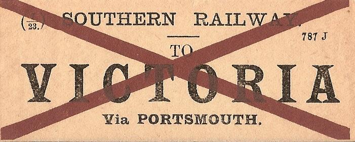
A Southern Railway luggage label combines both the red cross of the LB&SCR (indicating it has come from the
Isle of Wight), and the ex-LSWR's ''787'' stock code. Raymond Fuell
1976
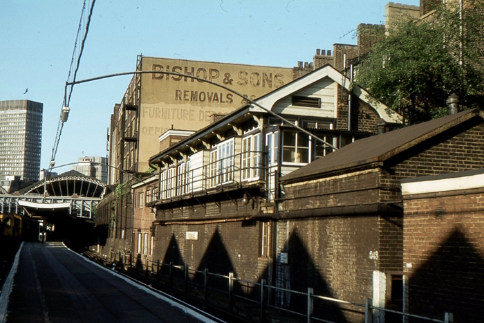
Victoria ''Eastern'' box formerly stood overlooking the southern ends of platforms 1 and 2. It was opened under
SE&CR auspices on 4th January 1920 as Victoria ''A'' Box, and boasted 200 pneumatic pull-out slides. It was
built to an in-house SE&CR design based heavily on those earlier Saxby & Farmer products of the previous
century. This same design was later continued by the Southern Railway for construction of new signal boxes
at Ramsgate and Aylesford. Victoria Eastern cabin went out of use on 13th May 1979, when control was
temporarily transferred to the 1939-opened signal box which controlled the ''Brighton'' platforms. The entire
terminus subsequently came under the control of the ''Victoria Panel'', based at Clapham Junction, on 9th
May 1980. The triangular shadows seen here are those of the Central Division station's trainshed.
© Roger Goodrum
1977
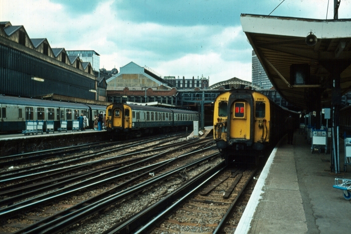
Unrefurbished 4 CEP units are the order of the day in this view of the Eastern Section platforms, which also
includes the full extent of the Central Section trainshed, before any redevelopment work commenced. On the
left is 4 CEP No. 7169, forming a boat train service to Folkestone Harbour, via Orpington, whilst on the right
is recently-arrived 4 CEP No. 7163. © David Glasspool Collection
1977
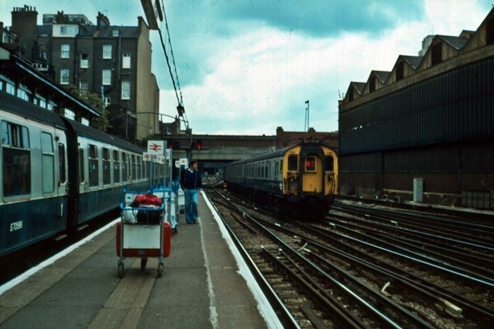
British Rail luggage trolleys abound on platform Nos. 1 and 2, as 4 CEP No. 7197 disappears underneath
Elizabeth Bridge. Notice on the left, above the roof of the stabled 4 CEP, the top of the ex-SE&CR signal
box. © David Glasspool Collection
<<Previous Next: the History Continues >>
Return to the Kent Rail Homepage or alternatively, check for Updates.
Website & Copyright information - Links - Contact the Webmaster
All content is copyright © David Glasspool unless otherwise stated